Optimizing Autofocus » History » Revision 6
« Previous |
Revision 6/11
(diff)
| Next »
Anchi Cheng, 02/16/2011 12:50 PM
Optimizing Autofocus
Focus, Z Focus, tomo Focus and other variation of focus nodes use the same Focus class but with different settings, focus sequence and position in the MSI sequence to achieve different effects. Each need to be optimized for your instrument and usage. The defaults we provide works for us but an understanding of how it works can help you having the smoothest run and getting the best data.
| Node Name | Found in Application | Prerequisite | Performance Target |
| Z Focus | all MSI | visible area on the grid | grid almost at eucentric height, defocus zero is no more than what Focus node can handle |
| Focus | most MSI | grid almost at eucentric height to allow using only defocus to make correction without significant beam shift | defocus zero is reset to within acceptable tolerance for final exposure |
| Tomo Focus | MSI-Tomography | grid close to eucentric height, defocus zero is at eucentric height | grid is accurately set at eucentric height |
What you should see during autofocus by beam tilt:
Here is an 512x512 example image pair acquired in Focus node at 0.14 nm/pixel at beam tilt separated by 0.8 mrad: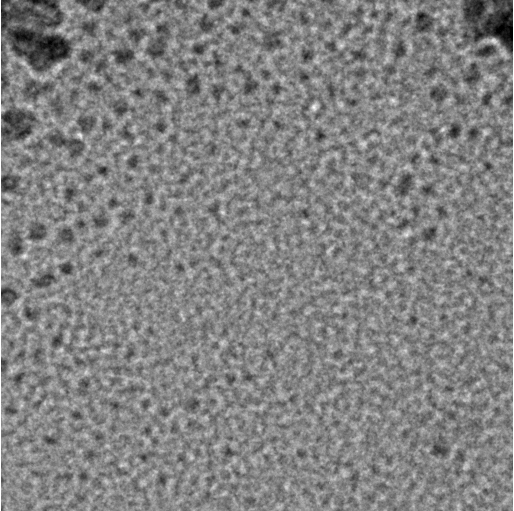 |
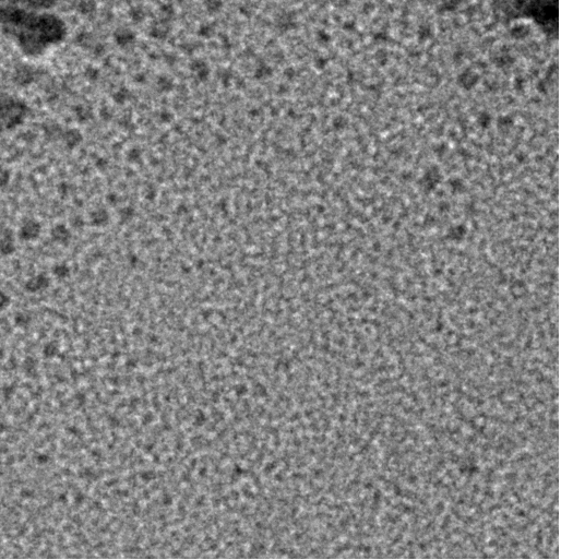 |
| focus1 image | focus2 image |
At Focus node of your MSI application, you can watch their display. Make sure that beam has not shift off the view (an indication of be Beam Tilt Pivot Point Alignment) and the contrast does not reverse (Objective aperture not centered or too small for the beam tilt applied).
In the same node, you can make it display the correlation like this: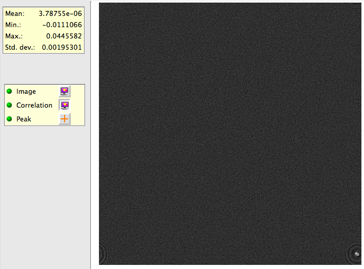
The correlation map shown in Leginon has origin (identical image correlation) at top left corner and is wrapped around so that peaks close to all corners means smaller shift than peaks close to the center of the correlation map. In this example, phase correlation is used, and focus2 is shifted from focus1 to the top-left by a distance of about 1/15 of the image. Therefore, we see a peak at bottom-right. and the phase correlation peak is sharp and with modulations around it.
You may notice that the peak is elongated. This is caused by the coma effect of the beam tilt.
< MSI Operation | Queuing option >
Updated by Anchi Cheng over 14 years ago · 11 revisions