Bug #2016
closedHow to get CTF data from database
0%
Description
From Scott:
Hey Neil,

I want to query values for ctf from the database for a frealign
refinement. Since you're flipping defocus axes and angle convention,
how do I do this properly? Is there a function in apCtf that will
take care of everything for me?

Thanks,
Scott
Files
Updated by Neil Voss about 13 years ago
Hi Scott,
That is a good question that I have thought long about.
ANGLES:
BEFORE: 50% of ACE2 values before the change had bad astig angles in radians, ACE1 did not insert angles (no astig), and CTFFIND had good angles, but in degrees.
AFTER: Now, all angles are in degrees.
DEFOCUS:
The order of the defocus does not matter to any of the programs, I just do the conversion, so that we have an internal convention that matters. So before and after are equivalent.
BEFORE: defocus1 or defocus2 could be a larger number.
AFTER: defocus1 is always less than defocus2. Astig angle is rotated by 90 degrees to switch order.
Neil
Updated by Scott Stagg about 13 years ago
OK. I think I understand, but I'm getting some inconsistent results. It sounds like you're saying that if I use the values directly from the database they will work directly with Frealign. In other words, if I use ctfdb.getCtfValueForImage() and convert the defocus values to angstroms, then df1, df2, and angast can go straight into the frealign param file. However, the apFrealign code is a little different:
                if ctfdata is None:
                    ctfdata, confidence=ctfdb.getBestCtfValueForImage(imagedata, msg=False)
                if ctfdata is not None:
                    # use defocus & astigmatism values
                    particleparams['df1']=abs(ctfdata['defocus1']*1e10)
                    particleparams['df2']=abs(ctfdata['defocus2']*1e10)
                    particleparams['angast']=-ctfdata['angle_astigmatism']
As you can see, it makes angast negative. Is that a bug or is that trying to account for the image origin problem? Anyway, I tested it with the way in apFrealign, and a reconstruction that was going to 4.8 A with ACE1 estimated CTF went to 5.8 with CTFFIND estimated CTF. Should I try again without swapping the sign on angast?
Updated by Neil Voss about 13 years ago
Oh, yeah, I think CTFFIND and FREALIGN use the negative of the database values. Despite the figure in the CTFFIND paper, Mindell 2003, showing the opposite. You'll note that we take the negative of the CTFFIND value after estimation, this has not changed since its initial implementation in myami 2.0 or whatever.
That is an interesting result on the resolution. I wish I could say more about it. You would figure that CTFFIND and FREALIGN would give the same results. This is something, I am doing for my paper, but it might be interesting to plot the CTFFIND defocus against the ACE1 defocus values.
Updated by Scott Stagg about 13 years ago
- File 11feb25b_00008enh.mrc2.png 11feb25b_00008enh.mrc2.png added
- File 11feb25b_08enh-plots.png 11feb25b_08enh-plots.png added
- File 11feb25b_00008enh.mrc added
- File 11feb25b_00009enh.mrc added
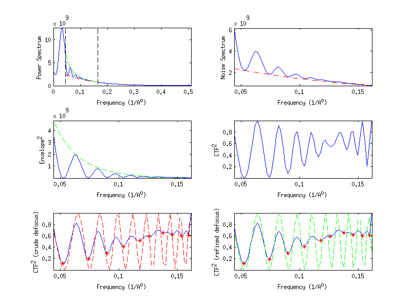
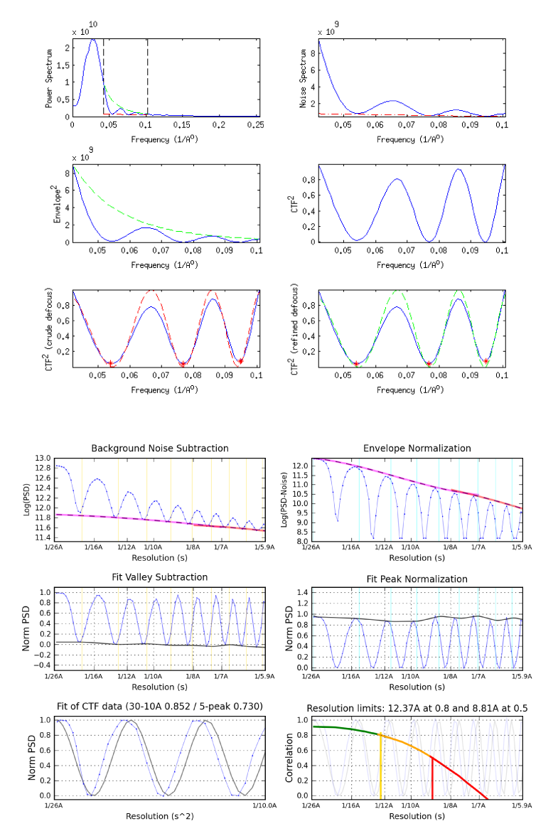
I did another test, and now I'm getting a very confusing result. I have some carbon images where zeros go out beyond 4 A, so I used that to compare ACE1 and CTFFIND. Upon initial inspection, it looked like both packages were doing terribly at estimating CTF, but I knew ACE1 was giving good results. So what I did was to compare the 1D graphs output by ACE1 to the 1D graphs produced by the new CTF software. I've attached the graphs to this issue. As you can see, the ACE1 graph shows a nearly perfect fit out beyond 5A. This disagrees with the graph produced by new CTF where it looks like CTF gets scrambled at fairly low frequencies. What do you think about this? To me, it looks like there is a bug with how you are simulating the CTF. On the other hand, what you showed at the workshop looked great. I also attached the result from CTFFIND. It shows a similar result with scrambling at low frequencies. I also attached two high res carbon micrographs so you can test the software out on your end to see if you get similar results. The microscope parameters for the micrographs are 120keV, 120,000X, 2.7 Cs, 0.65204 apix, 1.08 um defocus.


Updated by Scott Stagg about 13 years ago
Another piece of data...I swapped the sign on angast for the frealign reconstruction I was talking about above, and the resolution went to 5.4 instead of 5.8 that I was getting before. I guess that demonstrates that sign convention wasn't the problem. I feel like I'm using CTFFIND properly. I used the "fine tune previously estimated defocus" settings. I think all the high-resolution reconstructions used CTFFIND, so do y'all think the reason that it's not working great for me is the difference between CCD data and film?
Updated by Neil Voss about 13 years ago
I disagree the ACE1 fit (from its graph) goes awry at about 9 Angstroms. It is just hard to see, because the normalization is off.
I will try to test sometime, first class is tonight.
Updated by Neil Voss about 13 years ago
Also, the decay of signal around 8A (.12%) and then it comes back around 6.5A (.154) is usually evidence of astigmatism.
Updated by Scott Stagg about 13 years ago
I agree that the normalization is off with the ACE1 graphs, but what I'm looking at is the position of the minima. In the final ACE1 graph, there are overlapping minima in the simulated and calculated CTF all the way out to the end of the graph. In the new CTF graph, the minima start to diverge at the third minimum.
I'm sure you're right about there being some astigmatism.
Updated by Neil Voss about 13 years ago
- File scott-data.tar scott-data.tar added
Hi Scott,
I was playing around with the Cs and pixelsize, and I seem to get a better fit with a pixelsize of 0.63 A rather than 0.65 A, but not perfect. I am also wondering if the Cs is off a bit. I am not really setup to test it, I was just playing with the parameters during upload and comparing the final fit.
I use ACE2 bin by 4 and it had no trouble finding the CTF for any pixel size. Then I refined it with CTFFind3.
Updated by Scott Stagg about 13 years ago
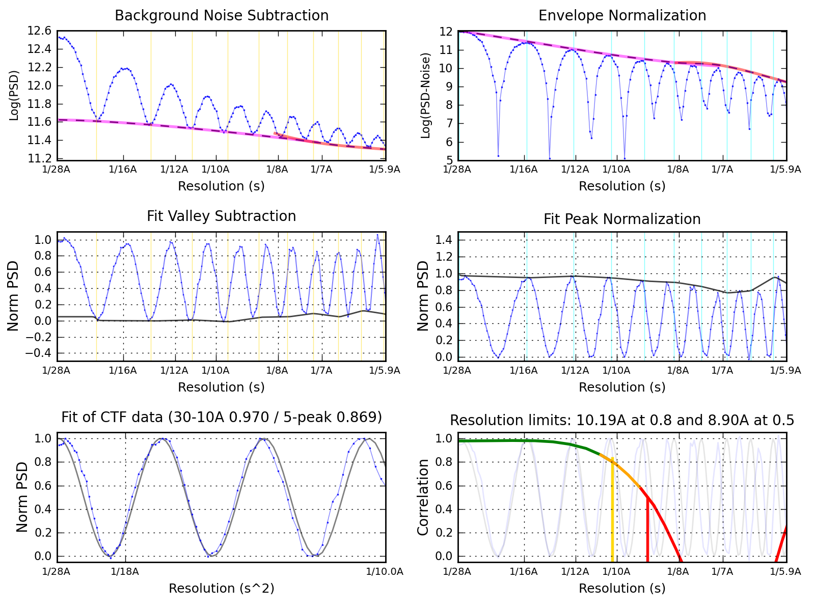
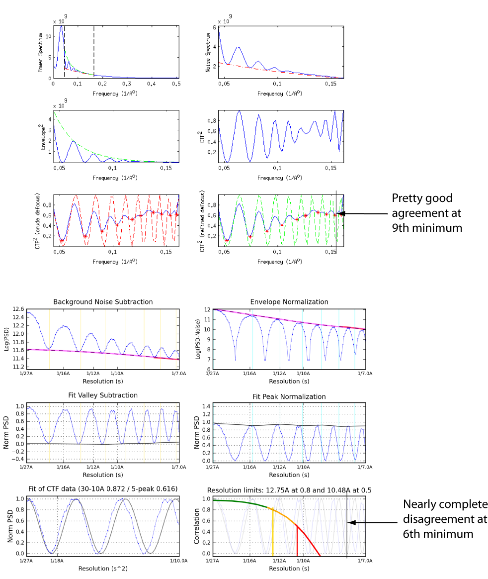
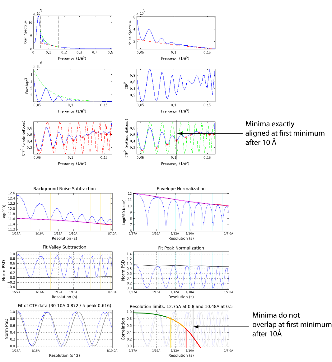
The more I think about it, the more I think that there is some disagreement between how ACE1 simulates the CTF in matlab and how you're doing it in python. Please see the attached figure. The top image shows the results outputted by ACE1, and the bottom is the same result outputted by new CTF. As you can see, when ACE1 simulates the CTF, there is agreement out to the 9th minimum. When new CTF simulates the same defocus, the minima diverge at the 6th minimum. Is it possible that there is a bug, or is this something even harder to figure out?
Updated by Neil Voss about 13 years ago
This is what I am seeing, good fit then bad, then back in sync. I think ACE1 might have missed a minimum. I just never liked those minimum finding functions...
Updated by Scott Stagg about 13 years ago
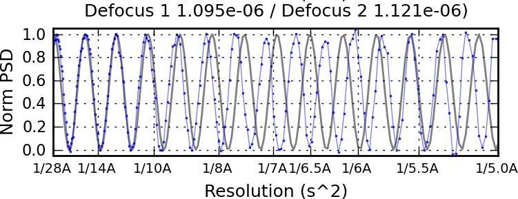
I feel like I'm not making myself clear. Your plot is from a different estimation that allows for astigmatism. What I'm saying is that given the same defocus values, your CTF simulation and the one produced by ACE1 in Matlab are different. You argued that ACE1 might be missing a minimum, so let's look at ones where there's no question about whether they are there are not. I attached an image that highlights the difference between the two simulations at the first minimum after 10 Å. I maintain that there is a difference between the two. This is not a difference in the normalization; it is a real difference, and the difference becomes more and more apparent with increasing spatial frequency.
Updated by Neil Voss about 13 years ago
Okay, your second image is convincing. The other one I had a hard time believing your argument about something we could not see.
Updated by Neil Voss about 13 years ago
ACE1 code from getgamma.m and getctf.m
gmma = 2*pi*(0.25*Cs*(lambda.^3).*(s.^4) + 0.5*defocus.*lambda.*s.^2);
ctf = (sqrt(1-A^2)*sin(gmma) + A*cos(gmma)).^2;
I think this uses a negative defocus???
<hr/>
so I quickly rewrote my python code to generate the CTF, so it uses the same equations above verbatim. Now the problem comes with the sign of the defocus...
What I found was that if I flip the sign of the defocus (for my original equation as well), it fits the data perfect. Now the question is, what is going wrong?
So, are you sure the images you send me are not over-focused? I reprocessed the CTF of my high-res virus data (~5.8 A) and it was happier before.
Updated by Neil Voss about 13 years ago
- File 10apr19a_10apr19a_024gr_026sq_05hl_07en_1-plots.png 10apr19a_10apr19a_024gr_026sq_05hl_07en_1-plots.png added
- File 11feb25b_11feb25b_09enh_1-plots.png added
associated images
Updated by Neil Voss about 13 years ago
- File deleted (
11feb25b_11feb25b_09enh_1-plots.png)
Updated by Neil Voss about 13 years ago
more convincing
Updated by Scott Stagg about 13 years ago
I suppose it's possible that the image is over focus. I will take a new carbon image where I'm positive it is underfocus, and I'll try again.
Updated by Neil Voss about 13 years ago
Thanks, I want to make sure this all correct.
Updated by Scott Stagg about 13 years ago
- File CTFSimulationComparison3.png CTFSimulationComparison3.png added
- File 12aug30a_00006ex.mrc 12aug30a_00006ex.mrc added
- File 12aug30a_00012ex.mrc 12aug30a_00012ex.mrc added
OK, I collected some new images that were definitely underfocus, and I'm still having the inconsistency between ACE1 and new CTF. See the attached figure. I also attached a couple of high res mrcs, so you can test on your end. Microscope parameters are like before: 120keV, 120,000X, 2.7 Cs, 0.65204 apix, ~.7 and 1.5 um defocus.
Updated by Neil Voss about 13 years ago
Hi Scott, based on the last results you are using an old version, could you please test on the latest version.
Updated by Neil Voss about 13 years ago
- Status changed from Assigned to In Test
- Assignee changed from Neil Voss to Gabriel Lander
So, here is the deal. ACE2 was (is still) using a non-standard definition of the CTF equation. I noticed this when trying to use CTFFIND/ACE1 parameters in ACE2correct it was missing the high resolution terms. So, I fixed the amplitude contrast in this bug, and it all went to hell. Today, I realized it was not just the amplitude contrast, but the whole equation was off.
So, what I am saying is that before today, Ace2correct was never accurately fixing CTF estimates from other programs. I think this was pointed out in Bug #2021.
In retrospect, a branch would have been a good idea, but the CTF pipeline was never supposed to be so internally inconsistent. Gabe is still reporting some issues with ace2 estimation, so hopefully that will get worked out.
Updated by Neil Voss about 13 years ago
- Assignee changed from Gabriel Lander to Scott Stagg
Updated by Scott Stagg about 13 years ago
- Assignee changed from Scott Stagg to Neil Voss
I just updated and ACE 1 is still having the same problem as before. The simulated plot of CTF for new CTF is different than the ACE simulation, and that is distorting the quality of the ACE1 fit despite the fact that ACE1 and CTFFIND are giving essentially the same defocus.
Updated by Neil Voss about 13 years ago
- File mallick05.pdf mallick05.pdf added
- File ace1_gamma.tiff ace1_gamma.tiff added
Hi Scott,
I did some investigative work on the ACE1 code.
Looking at source:trunk/appion/ace/getgamma.m and comparing the function to the equation 5 in the publication page 11 (see attached). The Cs is negative in the paper and positive in the code. It should be negative, it concerns me that maybe ACE1 is fitting the Cs wrong, it would be hard to see until you reach about 1/15Å resolution.
I don't know how to best test this.
Updated by Scott Stagg about 13 years ago
I can tell empirically that the current algorithm is getting the defocus correct out to beyond 6 Å. I would say that you should change nothing in the ACE1 code, and instead have a conditional in your new code that says if you're using ACE1, then when you simulate the CTF then you take the negative of the defocus. I assume that ACE is getting the defocus correct because it is essentially doing a double negative (switching the sign of both Cs and defocus). If you insist on changing the ACE1 code, then I could test it on the super high-res carbon images that are attached to this issue. However, I must insist that the new ACE code produce exactly the same defocus that it is currently producing. I don't care what is going on in the guts as long as it gets the answer right, and right now ACE1 gives the best results for ice images of any CTF program that we use.
Updated by Neil Voss about 13 years ago
Note: the CTF is not symmetric
CTF(gamma) != CTF(-gamma), unless the amplitude contrast is 0, which it is not.
Again, I am not sure this is it, I just found this discrepancy. I have tried all forms of the +Cs and + defcous on Anke's 30S data which goes out past 5 Ångstroms and has clearly visible particles. Having a +Cs fails the fit past 1/10A.
You are pointing out that the peaks don't match up and I think this maybe the cause. I do NOT want to change the code, because if you change it one place you could miss another; it is a steep slope. It should not effect the defocus estimate at lower resolutions, so there is no need to fix and long as it is working. But, in my opinion, it is impossible to see the ACE1 fit out very far.
Updated by Scott Stagg about 13 years ago
I think we need to have a conference call about this. You keep saying that ACE1 is not estimating the CTF properly past 10 Å, but empirical evidence says that it performs the best. Does everyone think we can get a Scripps, Berkley, and FSU conference call? It would need to be hosted by Scripps, I think.
Updated by Amber Herold about 13 years ago
I can work on setting up a call. Finding a time that works for everyone may be the hard part. Scott and Neil, can you suggest times that work for you?
Updated by Neil Voss about 13 years ago
I would like to investigate this some more. Let me write it up in a more coherent format. Because I am not really convinced myself. I still trying figure what the heck is going on, but I can get matches out to 5A.
My feeling is that as long as you are close enough you can get high resolution. For instance, I got a 5.8A virus with the wrong astigmatism angles from ACE2. From ACE1, it may use the wrong Cs in the estimation, but the EMAN1 uses the correct formula in the phase flipping, so all is good. There is just too many discrepancies to mention. If you look at ACE1's astig formula (in the paper), it is ridiculously wrong.
Also, I will NOT be making any changes to the code, because I do not have time.
Updated by Anchi Cheng about 13 years ago
I need to investigate this, too. I've confirmed that defocus of ace1 in database is indeed positive all the time but would like to know what the raw output is like and test run some images I took for this. Only if I can get ace1 to run here !!!.
Updated by Amber Herold about 13 years ago
I ran Ace1 on Goby a couple weeks ago, and had Sargis install missing libs on Guppy (see #2088) but I may not have tested on Guppy since then...